Contributed by Anthony Lopez.
Disclaimer: DO NOT WORK ON LIVE CIRCUITS. Your power supply should not be plugged in until you have completed the construction of this SPECIFIC build CORRECTLY. Electricity can kill you, regardless of the voltage applied.
Your “Cheap and Easy” Stir Plate:
Parts:
- I used a 6 volt Cell Phone charger as my power supply. Most of us probably have gone through a few cell phones over the last couple years, and just about any one should work in the 5-12 volt DC range. (They are all DC current)
- 4 inch computer fan. Mine was 12 volts DC.
- hard drive magnets. I only used one. You can also buy rare earth magnets online from a number of vendors. Neodymium magnets are cheap retail if you can’t find an old hard drive to scrap.
- 2 inch diameter steel washer.
- Some scrap wire will be helpful, however we’ll only need about a foot of black and red wire.
I got all of the above parts for free.
If you can’t source hard drive magnets, I would suggest checking out K&J Magnetics. When ordering from them, be sure you pay attention to the thickness of the magnet, since most of what they offer is magnetized through the thickness measurement.
From Radio Shack, you’ll need the following:
- 7″ x 5″ x 3″ Project Enclosure: Part Number 270-1807 – $5.99
- 25 ohm 3 watt Rheostat (aka Potentiometer): Part number 271-265 – $3.99
- 12 Volt DC/30Amp Rocker Switch with LED – Part Number 275-018 – $3.99
- Silver Tone Knob – Part Number 274-424 – $2.99
Part Totals: $16.96
If you aren’t soldering friendly, you’ll also need to pick up:
- 3/16″ Fully Insulated Quick Disconnects (16-Pack) – Part Number 64-3134 – $2.19
Apparently the design of the rocker switch may have changed, so as of 9-30-09 try these disconnects instead:
- 1/4″ Fully Insulated Quick Disconnects (10-Pack) – Part Number 64-4040 – $1.99
That brings us up to about 19 dollars total. I tried to make sure that all parts that I purchased were easy to come by at a Radioshack so that people won’t have to substitute.
From the hardware store, we’ll need:
- (4) 2.5 inch 10/32 bolts)
- (12) 10/32 nuts
- (4) washers to fit the 10/32 bolts.
Please Note: A 10/32 Bolt designates a size #10 with 32 threads per inch. You can also choose #10-24 bolts, but make sure you use the correct nuts. A 10/32 bolt is NOT a 5/8″ diameter bolt.
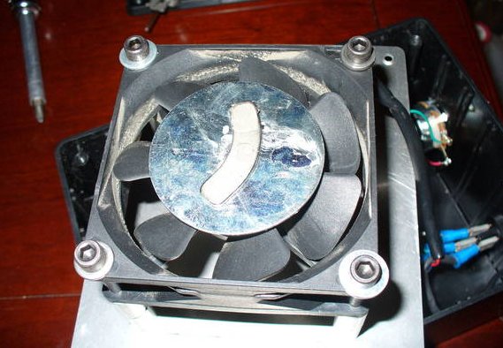
The most important part of all of this is using the steel washer. By gluing the washer to the fan, you are adding magnetic point for your magnet to stick to without gluing it. This will allow you to fine tune the plate before gluing down your magnet (They won’t come off very easily once glued) Also, if you decide that you want to use a larger or smaller stir bar, you can add or remove magnets and center them correctly without having to scrap your fan.
Steel Washer & Magnet Placement
Steel Washer placement & Magnet
I drilled my holes for the potentiometer and the switch on the 5″ x 3″ side of the project enclosure to allow for more mounting space for the fan. Mount them up using the enclosed hardware that came with both of them. I also drilled a hole on the bottom corner of the enclosure to run the power supply out of the box.
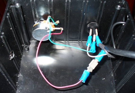
Wiring Overall View
First things first: Wiring-
Get your Black and Red computer fan wires stripped. If you aren’t soldering, put a female quick disconnect onto the Red wire.
Next, cut off the power supply “phone” side and try to keep the power cord going to the wall socket as long as possible. This just makes things easy if you make a mistake. Some phone chargers will have two wires, while others I’ve found have a “braid” going around another insulated wire. The “braid” is our ground or negative and the inner cable is your power side. For the chargers with 2 single wires inside, black is your ground.
Strip about 1/4” of the insulation off your wires. Take the black cable of your computer fan and the black cable of your power supply and twist the exposed wire together and insert them into one of the female quick disconnects. Make sure that you have already put your power supply cable through the hole you drilled in your enclosure before making this crimp or you won’t be able to close your enclosure when you are done. Connect these two wires to the “Earth” male connector on your power supply.
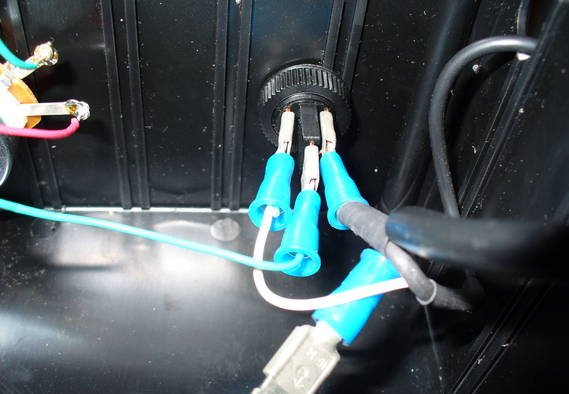
Now, take your Red cable from your power supply and add a female disconnect onto this cable and attach it to the “male” terminal on your power switch labeled “Supply”
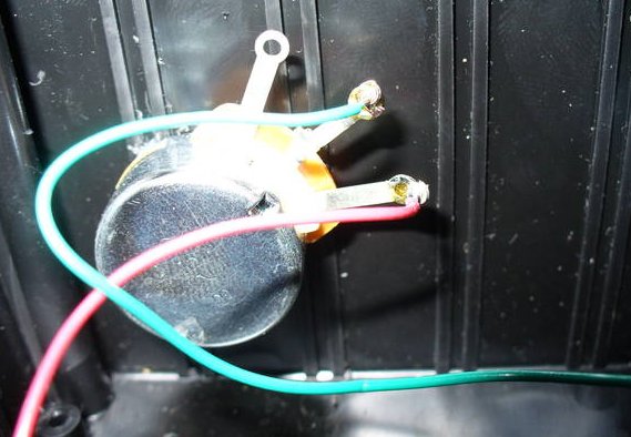
We are ALMOST done with all the wiring. The only male terminal left on our power switch is the one labeled “Load”. Take some of the spare wire, about 4-5 inches, and strip off the insulation from each end. Attach a female disconnect to each end. Now, attach one side of the wire onto the “Load” terminal on your power switch, and the other to the center pin of the potentiometer.
The last step is to take the “Power” cable (red) from your computer fan and attach another female disconnect. Attach this disconnect onto the right side pin on the potentiometer.
Potentiometer Wiring
Power Switch Wiring
Assuming everything has been done correctly, plug in your power supply, flip your power switch to the “On” position, and try turning the knob on the potentiometer back and forth. You should be able to observe the fan speeding up and slowing down as you turn the knob back and forth.
Now, we need to take the steel washer and glue it onto the fan. I used some 60 second epoxy so that I could turn the fan on and off to observe if the washer was centered on the center of the fan.
The next steps in this project is to fine tune the positioning of the fan within the enclosure, and try magnet combinations and positions until you get your bar spinning correctly.
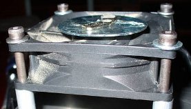
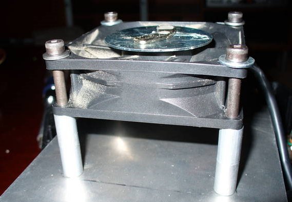
I used 2 ½ inch 10/32 bolts with matching nuts and washers to mount my fan. I also used some ¾ inch stand offs to raise the fan. Instead of the standoffs, you can use extra 10/32 nuts to position the fan up and down the bolts. I also found that you need to drill out the holes of the fan to get the bolts through. 8/32 bolts will work without drilling.
Mounted Fan
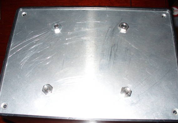
Bottom Side of Aluminum plate with fan mounted and secured.
Your project enclosure should have come with both an aluminum and a plastic sheet to close up the enclosure. I drilled out the pattern for my fan’s mounting holes into my aluminum sheet, and then mounted the fan. Once I had everything drilled out and mounted, I put every thing together, and tried it out…
